
Validating Theoretical Creep and Fatigue Simulations for a Custom Laptop Holder
A simple Slot to hold 17mm laptops to prevent desk clutter

This Project served two purposes, to improve the unorganized nature of my desk, and to compare physical material properties against simulated values. I use my laptop to support two external displays when I am at my desk while also taking it to class every day. When I am using it at my desk it does not need to be open or on the desk so the holder serves as a place for it to safely sit while charging and connected to the monitors. It solves the problem of accessibility by living in a convenient spot on the side of the desk allowing for easy unplugging and packing. The design is simple and was made for the ease of 3D printing without supports and on a single plate.


This was printed with ABS at 30% infill with a gyroid infill pattern to ensure that the stiffness and strength are adequate. It was printed in three parts, both main arms are identical and a spacer/cross brace was added to improve stability. The arms have an angled lip so inserting the laptop is easier as they guide it into place. At the bottom of the arms is a small subframe of a thick semi-circle to add rigidity when flexed. The cross bracing part has two purposes. It first makes instillation much easier by fixing the alignment and spacing of the two arms before securing them to the desk. It also hugs the top face of the desk while pressing against the adjacent desk support to decrease the flex of the arms left to right and rotation forward and backward.


The previously discussed designs were final and the same as used in the following analysis section. Since this laptop holder would be used every day, I wanted to simulate how the holder would perform over time under the constant load of my laptop. The simulations were validated after twelve months of consistent use to determine the error between theoretical and experimental values of creep and fatigue.
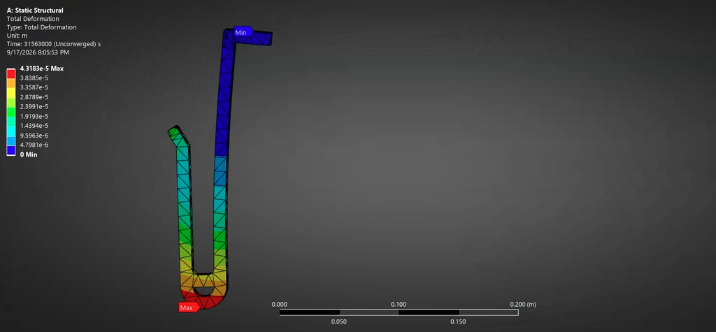
Under a constant load of 7.769 newtons (half of the laptops weight) and over a year the simulation determined that the maximum displacement was 0.043103 millimeters. After multiple measurements with my calipers I obtained an average difference of 0.02 millimeters from the original CAD files. I am not satisfied with this result as my means of measurement contribute to most of the percent error. Depending on the force I applied to the calipers changed the values drastically and it proved to be very difficult to measure to more than two decimal places. For future testing I will perform a similar experiment on a part that is much more subject to creep so that the total displacement is measurable.