Absolute Position Correction for GPS Denied Autonomous Quadcopter Visual Inertial Odometry System
Using an NVIDIA Jetson Orin Nano, Arducam IMX477, and DJI Phantom 3 to calculate absolute position from satellite images matched against camera frames.
While there are many common navigation systems, they all have limitations. Visual Inertial odometry is a somewhat common form of navigation that does not require a GPS. The idea of map to frame matching serves a visual inertial odometry system with and absolute position fix to limit the overall error drift. This project builds a navigation system that needs no radio link, no ground station, and no external signal at all. We decided to build a first prototype that focuses on just the satellite image matching to then implement on a future full VIO system.
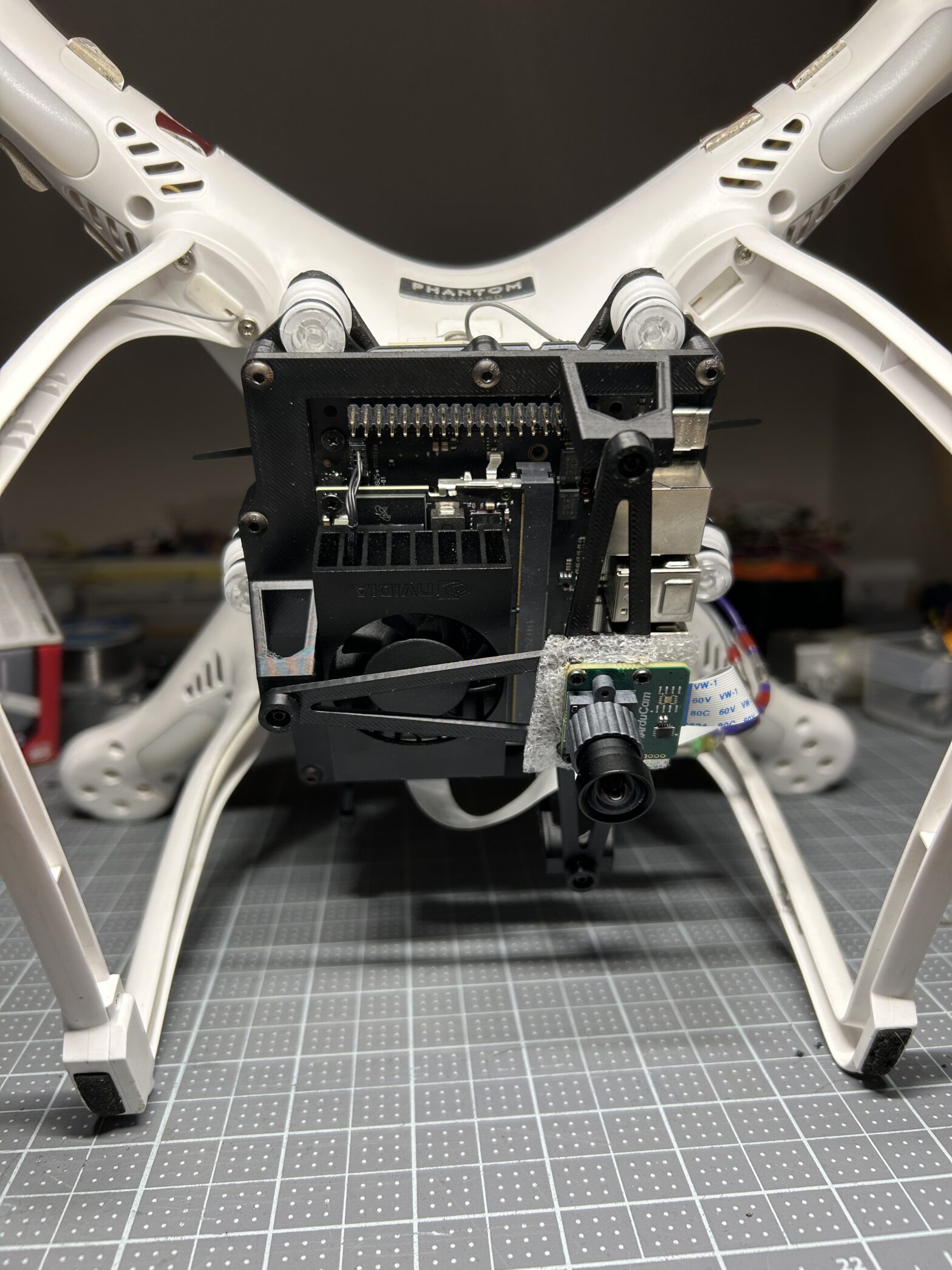
This was built on a modified DJI Phantom 3 carrying an NVIDIA Jetson Orin Nano and an Arducam IMX477 in order to keep initial costs cheap while we improved the software. Our design process included material selection, weight and frequency optimization, and static force simulations after defining the main constraints.
To determine our weight constraint we designed and 3D-printed a coin slot mount to sit exactly where the real payload would. Then loaded it incrementally with quarters between test flights to find the maximum weight the airframe could still handle.
In order to capture usable frames in flight, motor and blade-pass frequencies were characterized and used to tune the mount to an 18 Hz isolation frequency at a damping ratio of 0.12. Using given data on the DJI motor’s RPM we had to balance vibration between idle and hover while determining the damper stiffness to resist sway.
These tests translated to a required damper stiffness of 0.6 N/mm across a 6-damper hexagonal pattern at a 285-gram mass target.
After a few draft designs, I preformed a static force analysis on the main mounting plate. The load case was 4x gravity to simulate a worst case rough landing scenario.
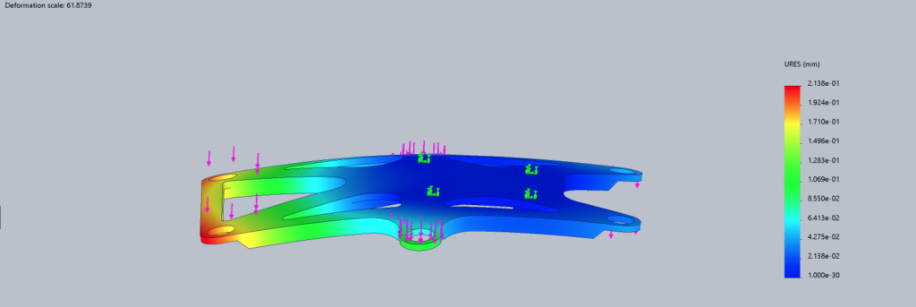
With the design validated to a maximum displacement of 0.2mm under the worst load case, the final modifications were made and the full assembly was created.
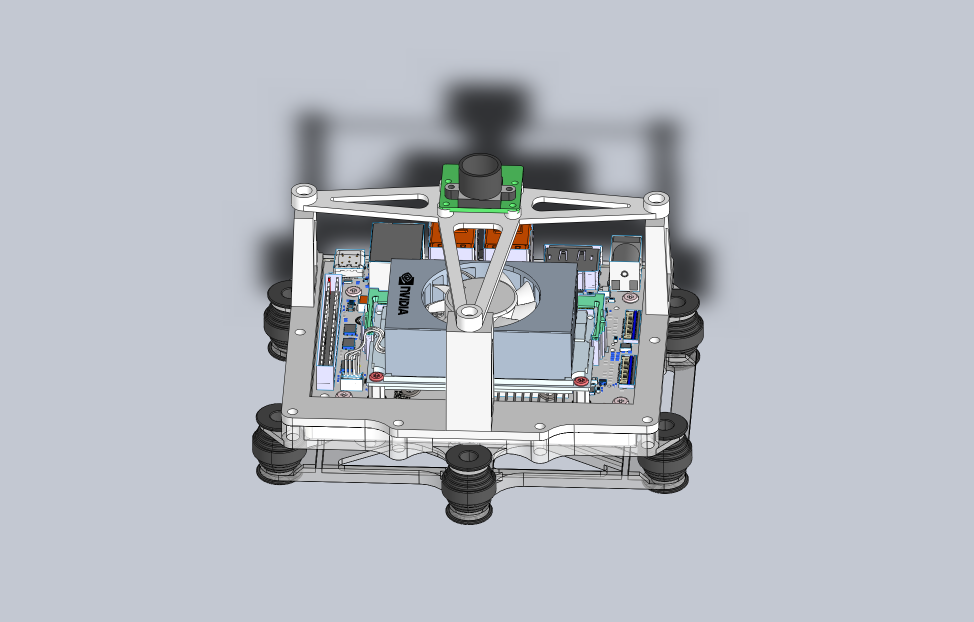
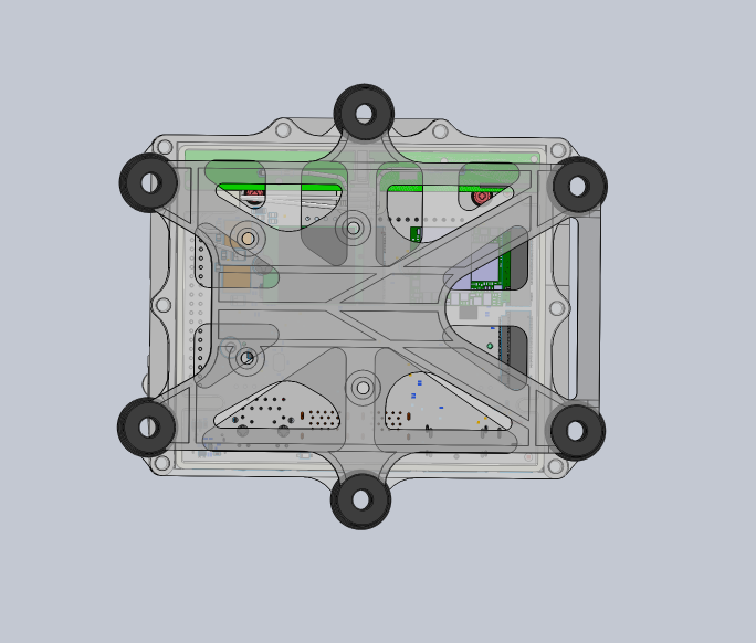
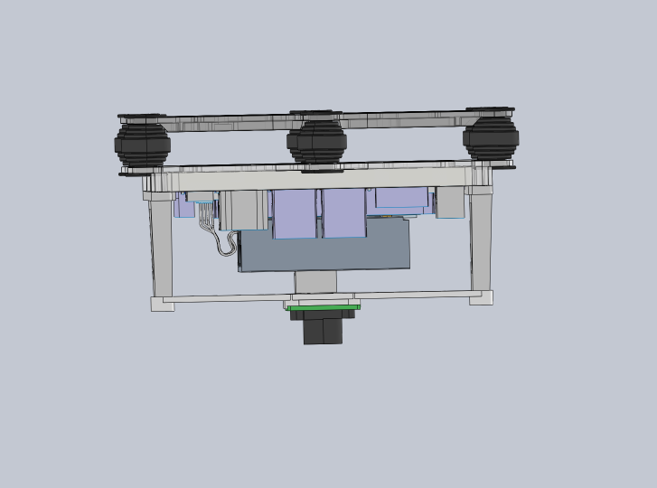
All of the parts where then printed, assembled, and mounted to the DJI. M3 screws with brass heat set threaded inserts secure the jetson plate, and M2 screws secure the camera strut. All threads received threadlocker to survive the high frequency vibration.
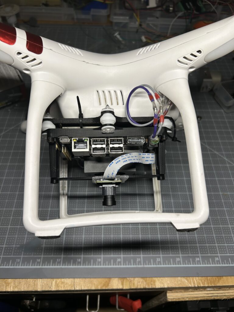
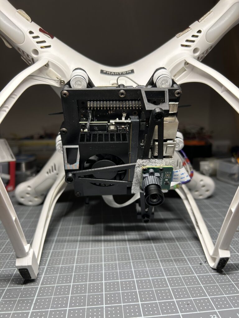
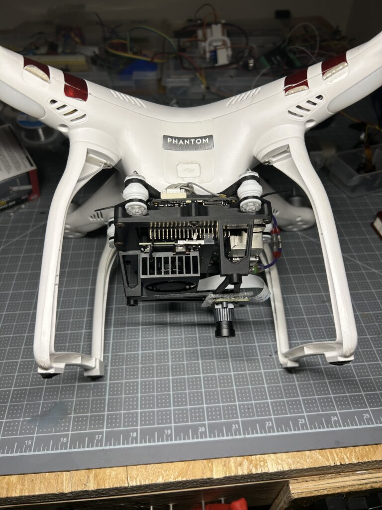
The general software pipeline consists of 9 python scripts running in a ROS2 environment on the Jetson.
First is image correction, raw sensor data from the CSI camera is converted to a usable frame through the Jetson’s hardware ISP. Lens distortion is corrected and resolution is reduced. Contrast is then normalized with CLAHE, splitting the image into an 8×8 grid and equalizing each region independently. Next is positioning the reference satellite imagery. Nine satellite tiles are stitched into a single mosaic before matching. A single tile only covers about a quarter of the camera’s ground footprint so the mosaic is necessary. The mosaic receives identical CLAHE treatment to the live frame. After that feature detection and matching happens. ORB reduces both images to sets of distinctive points with binary appearance descriptions. Each point’s orientation is computed from its local intensity, which is what lets features match regardless of the aircraft’s rotation. For every frame feature, the two closest reference candidates are found. Then a two step filtering process happens. Lowe’s ratio test keeps a match only if the best candidate is clearly better than the runner up. Surviving matches then go through RANSAC geometric verification, which tests whether they collectively agree on one consistent transform. Lastly, position recovery. With the main assumption that all features lie on the same plane, the camera’s position is recovered directly from the transform and checked by reprojecting the reference points and measuring the disagreement.
Results:
After seven flights across two months of bench and field testing, the vibration isolation performed as designed with clear, usable frames. The added payload had no noticeable effect on the Phantom’s flight agility, exceeding expectations for rigidity and strength. After iterating on launch parameters and pipeline fixes, the system produced its first accurate position fix roughly two months in. Accuracy improved most from two factors, sourcing current satellite tiles and flying over sites with clear, high-contrast ground features. The final two flights landed within 10 meters of the true flight origin, against an overall average error of 8 meters measured against DJI’s onboard GPS as ground truth.
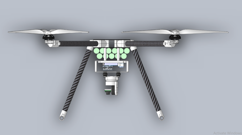
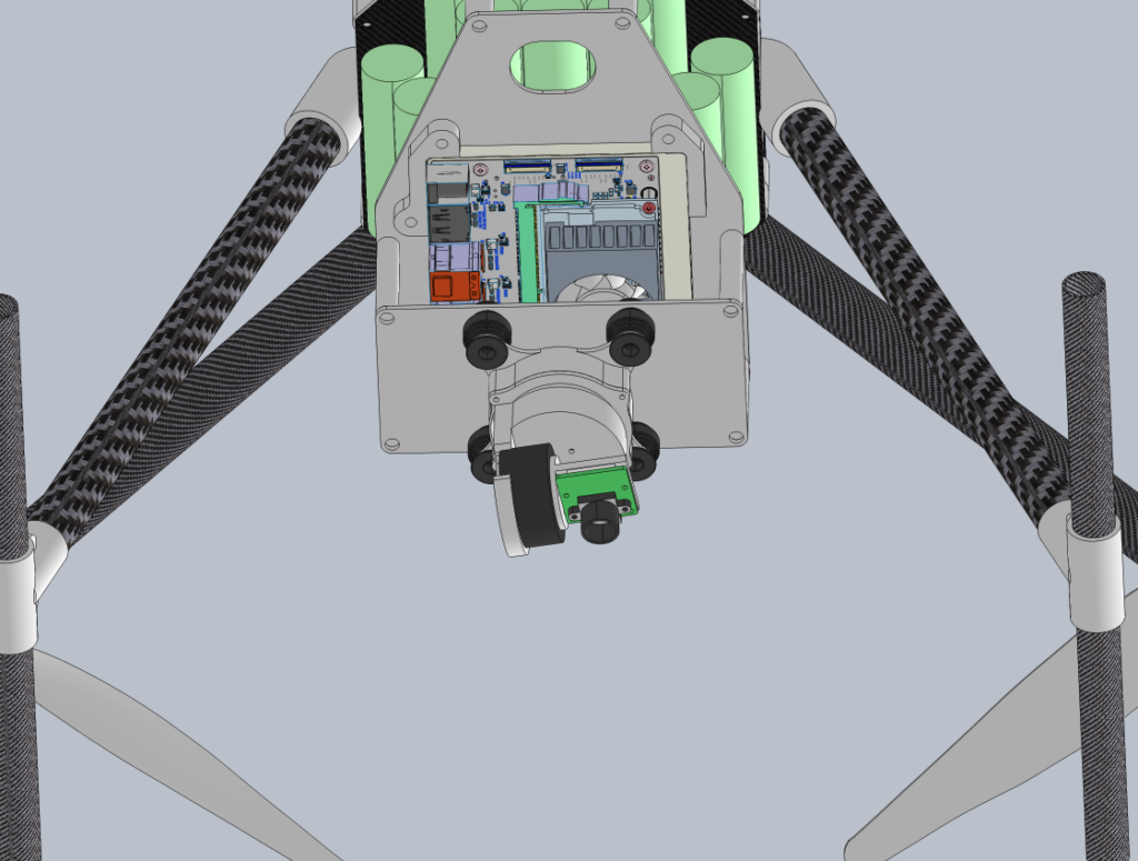
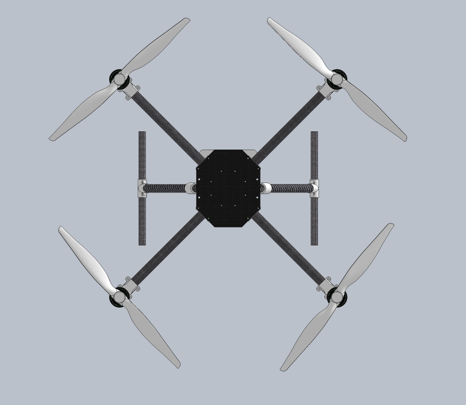
For the next prototype we have decided on three main additions to reduce the homography from a full 3D transform to an easier 2D one. A laser rangefinder for direct altitude measurement, replacing the current altitude estimate. An IMU for real orientation data, supplying pitch and yaw independently. And a two-axis camera gimbal to hold the camera nadir regardless of aircraft attitude, removing perspective distortion. We have already started on the CAD drafts and hope to continue this project when we can gather up the funds.