IoT Door Lock
Using an ESP8266 and motor driver to control a stepper motor to remotely lock doors over WiFi.

After moving into a new house at the start of my sophomore year of college with doors that only lock from the inside and nosey new roommates, a new lock was needed. The initial requirements for the lock where remote accessibility and durability/longevity to insure an easy and reliable way to secure my room.
Design Process
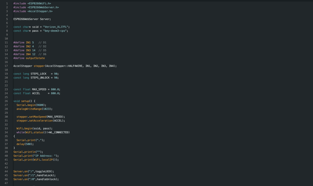
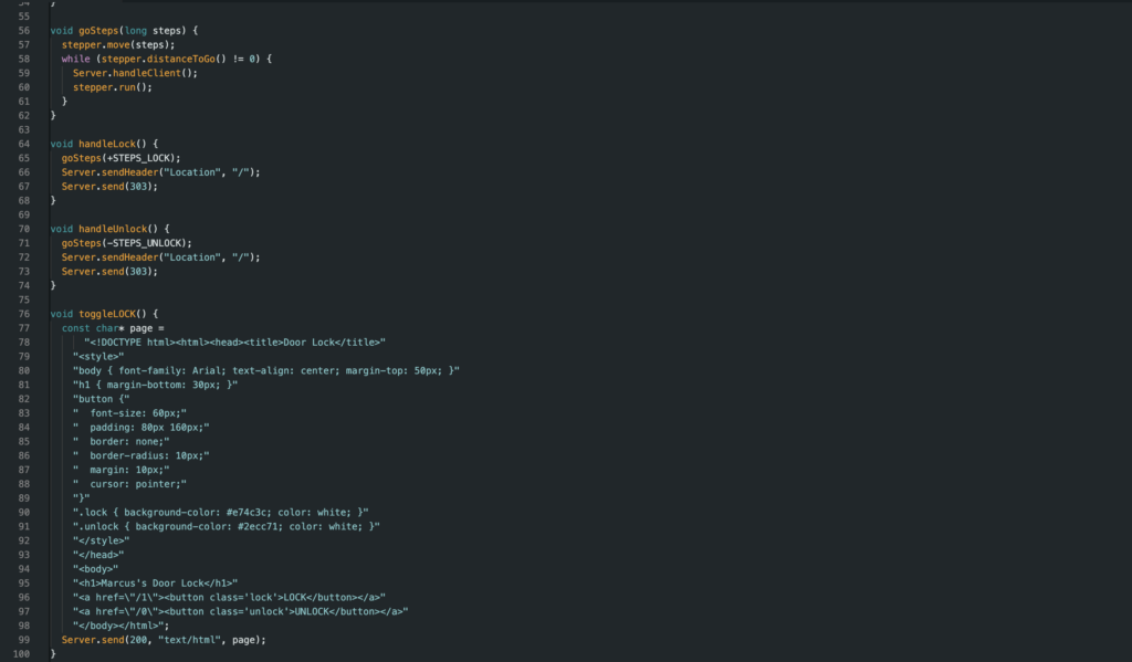
For every version I wrote all the code in the Arduino IDE using a combination of C, HTML, and CSS. The housing for the electronics was designed in Fusion 360 and then printed out on my babu labs P1S. I’ve used fusion 360 for each version of this project while making improvements to the design.
The design started with taking measurements of the components including the ESP, L928N motor driver, nema 17 stepper motor, power adapter, and the deadbolt itself. After gathering all dimensions, started the design of the motor mount and electronics housings in Fusion. Then moved to the Arduino IDE to work on the script for the ESP. The motors are controlled by analog signals from the ESP. When the ESP is powered on the page can be accessed by typing in the IP into a URL.
Iterations
The first version was created using a barrel bolt and servo motor while the website was only two styleless buttons. I experimented with a few mechanisms to accurately control the latch converting the servos radial motion into a linear action. I started with a rack and pinion and when the rack didn’t have enough travel, I tried adding two gears to increase the rpm of the pinion. These designs got better over time, but a large limiting factor of the lock’s effectiveness was that doors don’t always close in the exact same position or even close fully flush with the trim. This made it very hard for the latch to accurately close in the strike since there was only a few millimeters of space.
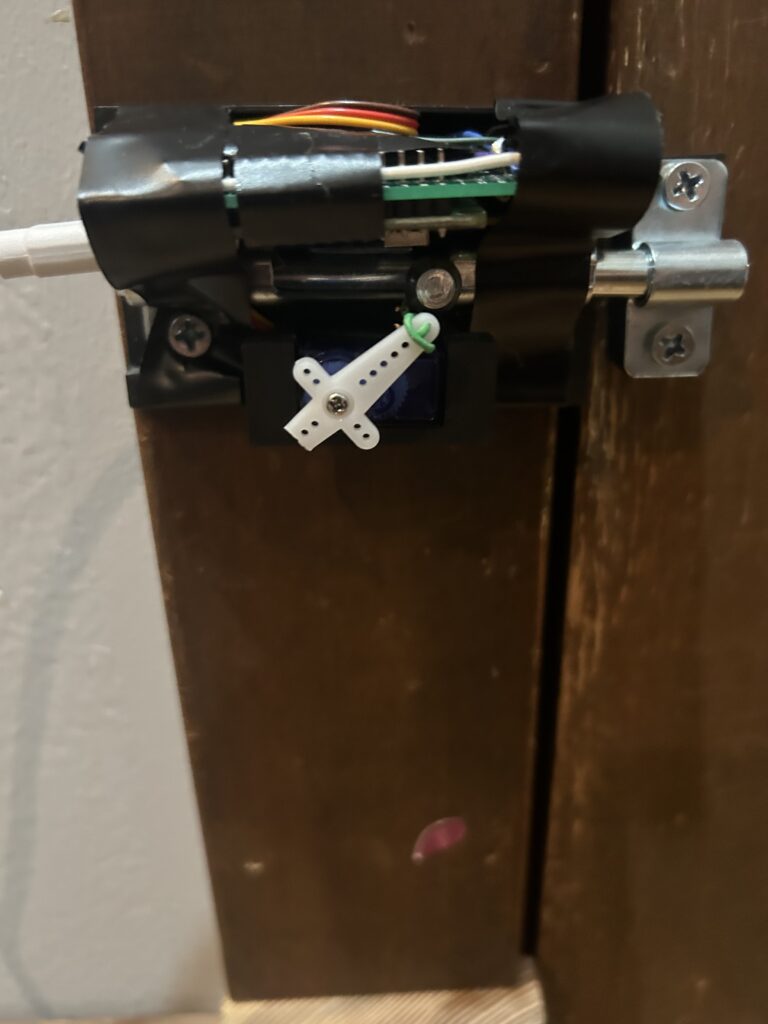
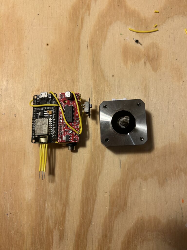
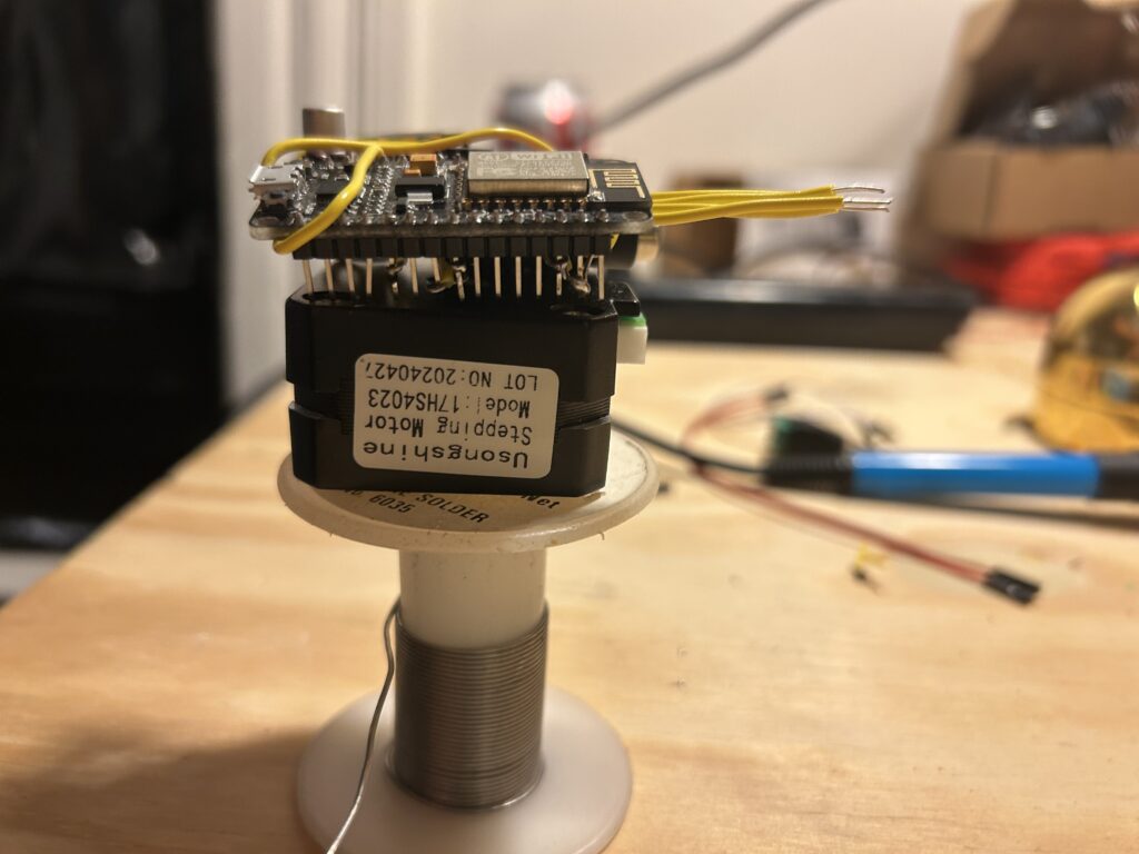
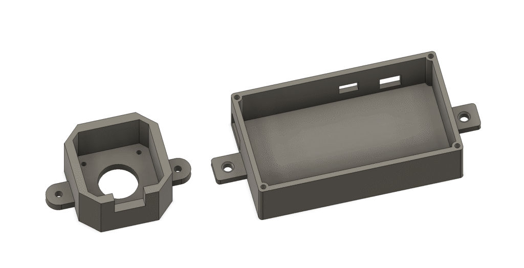
After moving on from the Barrel bolt idea I thought of a design that could be applied to almost any door. I decided that this version would tap directly into the deadbolt. The new design required more torque that the little nine-gram servo couldn’t achieve so I opted for a nema-17 stepper motor. This required a new housing and the addition of a motor driver.
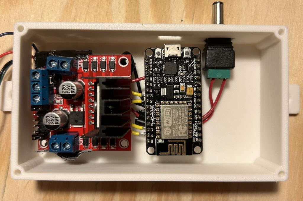
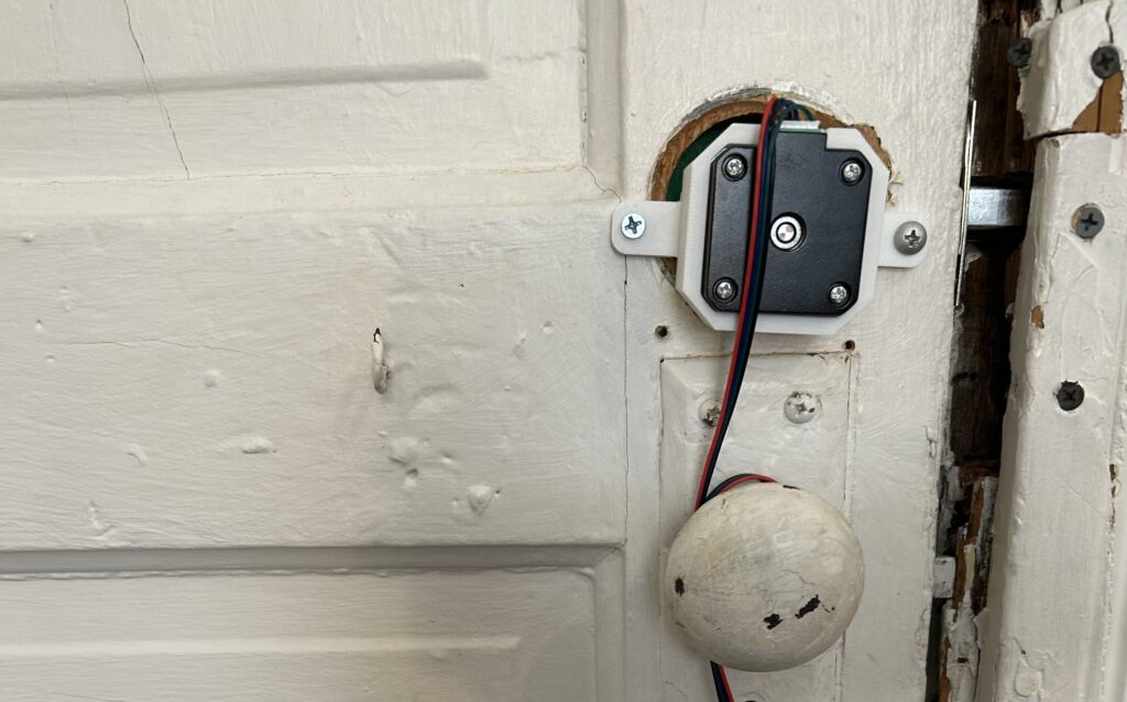
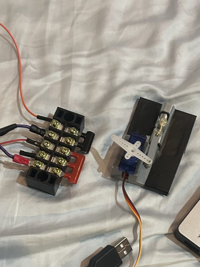
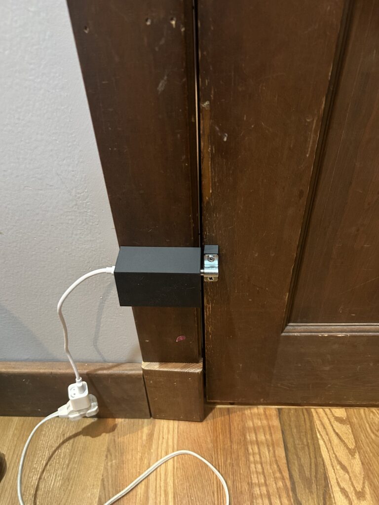
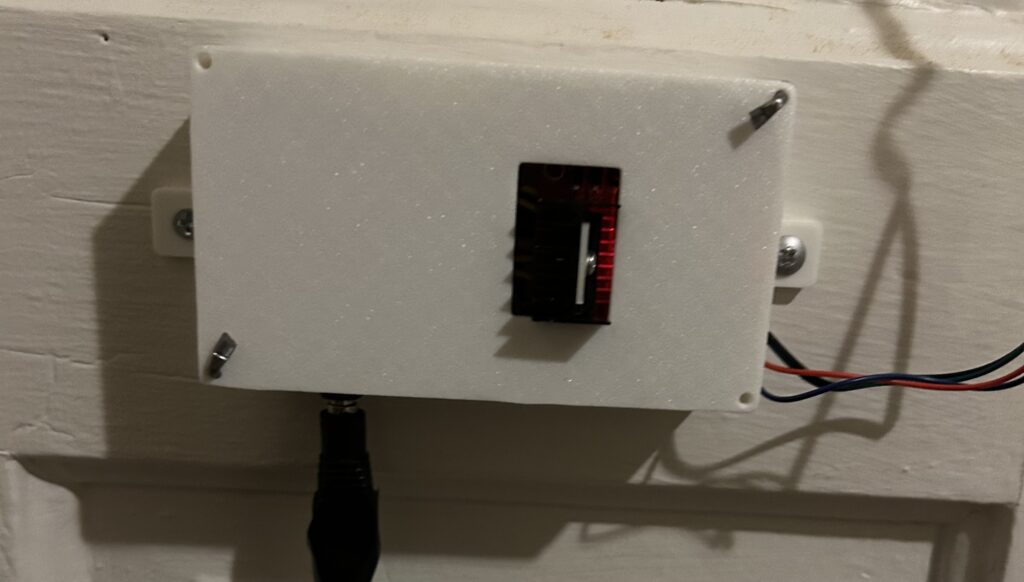
That brought me to version two. Using the same ESP but now with a L298N motor driver and stepper motor I had to update the design. The new motor driver and motor where significantly larger so I had to design a separate box to house the driver and ESP while the stepper was attached to the deadbolt. With this design the shaft of the stepper motor has a small coupling with a flat key that inserts directly into the deadbolt’s cam slot. Everything in this design worked flawlessly and has performed continuously since implemented in August 2025.


After the second version the only thing left to fix is the size and design. The third version is still in progress though the major changes come from using a new motor driver which is roughly half the size. this should allow me to change the design to a single part that contains all of the electronics and can be installed in one step similar to how the current motor is mounted.